IEC 60439, the standard for low-voltage switchgear and control gear assemblies, was under restructuring from the last decade. The new series of IEC 61439 standards were published in January 2009. This standard has brought considerable clarity in technical interpretation.
The IEC 60439 standards were ambiguous about how to assess compliance of partially type tested assemblies. As a result, manufacturers and testing bodies often treated partially type-tested assemblies differently. One of the main features of IEC 61439-1 is that the discrimination between Type Tested Assemblies (TTA) and Partially Type Tested Assemblies (PTTA) has been eliminated by the verification approach. Also the well known seven type tests increasing to 12 design verification characteristics.
The three different but equivalent types of verification
methods are introduced and these are:
Design Verification
The 12 design verification characteristics are split down into two main areas, that of ‘construction’ and ‘performance’.
The construction tests cover such areas as:
The performance areas cover, among others:
After successfully completing all 12 design verification characteristics, the benchmark will be set for future adaptations of the design, since IEC 61439 now accepts both verification by design rules and verification with a reference design, when carried out in line with the standard, are equal and equivalent to verification by test.
StandardTitle
IEC 60947-1Low-voltage switchgear and controlgear – Part 1: General rules
IEC 60947-2Low-voltage switchgear and controlgear – Part 2: Circuit-breakers
IEC 60947-3Low-voltage switchgear and controlgear – Part 3: Switches, disconnectors, switch-disconnectors and fuse-combination units
IEC 60947-4-1Low-voltage switchgear and controlgear – Part 4-1: Contactors and motor-starters – Electromechanical contactors and motor-starters
IEC 60947-4-2Low-voltage switchgear and controlgear – Part 4-2: Contactors and motor-starters – AC semiconductor motor controllers and starters
IEC 60947-4-3Low-voltage switchgear and controlgear – Part 4-3: Contactors and motor-starters – AC semiconductor controllers and contactors for non-motor loads
IEC 60947-5-1Low-voltage switchgear and controlgear – Part 5-1: Control circuit devices and switching elements – Electromechanical control circuit devices
IEC 60947-5-2Low-voltage switchgear and controlgear – Part 5-2: Control circuit devices and switching elements – Proximity switches
IEC 60947-5-3Low-voltage switchgear and controlgear – Part 5-3: Control circuit devices and switching elements – Requirements for proximity devices with defined behaviour under fault conditions
IEC 60947-5-4Low-voltage switchgear and controlgear – Part 5: Control circuit devices and switching elements – Section 4: Method of assessing the performance of low energy contacts. Special tests
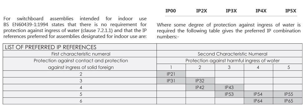
BS EN 60529 describes a system for classifying degrees of protection provided by enclosures of electrical equipment with a rated voltage not exceeding 1000V ac and 1500V dc. The markings used to indicate the degree of protection consist of the letter IP (Ingress Protection) followed by two characteristic numerals. The first characteristic numeral designates the degree of protection with regards to solid objects.
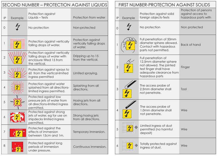
The second numeral designates the degree of protection against the ingress of liquid. It is intended to provide an indication of:
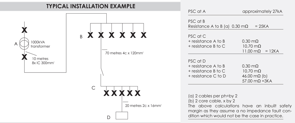
An estimation of the prospective short-circuit current (Psc ) in an installation is an important consideration in the selection of the appropriate protective device. The magnitude of the short-circuit current (rms value of the ac component)at a point in the installation will depend upon
It is possible to arrive at a maximum prospective short circuit value at the origin by taking the transformer kVA rating and its reactance and calculating from the expression:
To calculate the resistance in the LV circuit, obtain details of lengths and sizes of cables between the source of supply and the point under calculation. Using the table, opposite, determine the sum of cable resistances and then simply read of the estimated fault current from the relevant transformer curve on the graph opposite. The values assume a symmetrical fault across the three phases .In a single circuit, for line to neutral faults, take the cable resistance value from the table and double it.